Output Devices
-
Individual Assignment:
- Add an output device to a microcontroller board.
- Program the microcontroller to control the output device.
- Define specific actions or behaviors for the output device.
Designing custom board
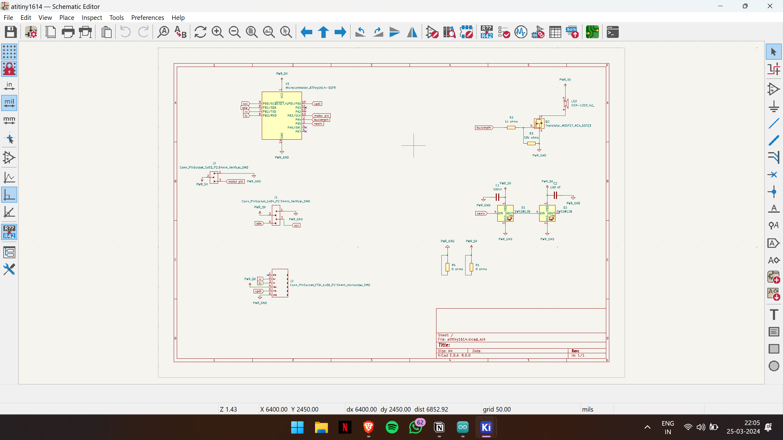
For this week's project, I planned to create a custom board featuring a buzzer, a servo motor, two neopixel LEDs, and an OLED screen. I began by designing the schematic layout.
I started with KiCad, and here is the output of the schematic design.
Then I continued with the PCB editor to draw the traces. Here is the output after routing the necessary tracks.
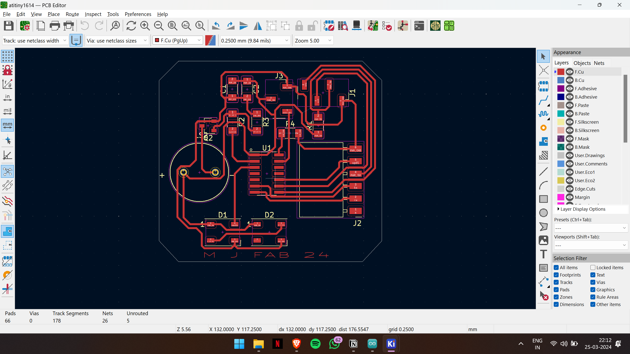
Then I exported the Gerber file and milled the PCB. For detailed documentation, refer to the Electronics Production week.
Below is the pin configuration for the ATtiny1614 microcontroller, which I'll be utilizing throughout this week.
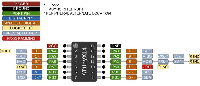
This week, the output devices I'm employing are dependent on PWM (Pulse Width Modulation) signals for control. It's essential to grasp the concept of PWM signals for a comprehensive understanding of their functionality.
PWM Signals
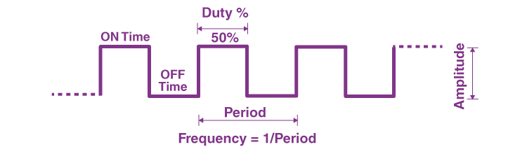
PWM (Pulse Width Modulation) signals are commonly used in microcontrollers to control the operation of various output devices such as motors, LEDs, etc. PWM works by rapidly switching a digital signal on and off at a fixed frequency, where the proportion of time the signal is on (duty cycle) compared to the total period determines the average power delivered to the load.
Here's a breakdown of how PWM signals work and their application in controlling output devices:
- Basic Operation : A PWM signal consists of a repeating cycle, where the signal is ON for a portion of the cycle (the duty cycle), and OFF for the rest. The ratio of ON time to the total period of the cycle determines the average voltage or power delivered to the load. For example, if the duty cycle is 50%, the signal is ON half the time and OFF half the time, delivering an average power that is half of the maximum.
- Frequency and Duty Cycle : PWM signals have two main parameters: frequency and duty cycle. The frequency determines how often the signal repeats, typically measured in Hertz (Hz), while the duty cycle determines the percentage of time the signal is ON within each cycle, usually expressed as a percentage.
- Controlling Output Devices : PWM signals are widely used to control the speed of motors, the brightness of LEDs, and the heating level of heaters. By varying the duty cycle of the PWM signal, you can effectively control the average power delivered to the load. For instance, in motor control, a higher-duty cycle will cause the motor to run faster, while a lower duty cycle will slow it down.
- Microcontroller Implementation : Most microcontrollers have built-in hardware peripherals specifically designed for generating PWM signals. These peripherals typically include timers/counters that can generate PWM signals with precise frequency and duty cycle control. Microcontroller datasheets and development environments provide APIs or libraries to configure and control PWM signals easily.
- Advantages : PWM signals offer several advantages, including efficiency (since power is only delivered when needed), precise control over output devices, and compatibility with digital control systems.
Next, I began by adding one component at a time and testing its functionality.
Servo motors
Anatomy of a Servo Motor:
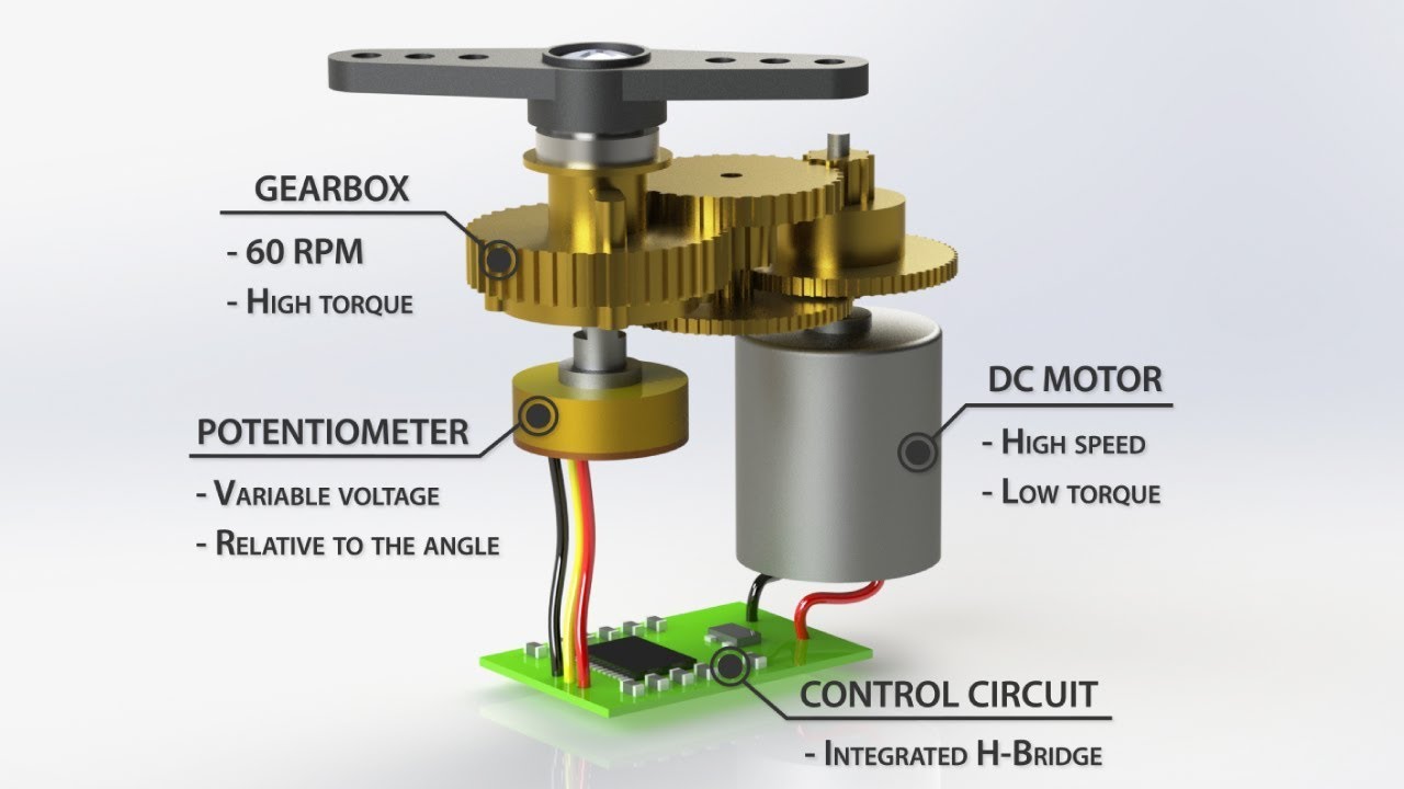
- DC Motor : Servo motors typically use DC motors as their primary source of rotational motion. These motors can be either brushed or brushless, with brushless motors being more common in modern servo designs due to their higher efficiency and reliability.
- Gears : The output shaft of the DC motor is usually connected to a set of gears. These gears help increase torque and reduce the speed of rotation, allowing for finer control over the motor's movement.
- Feedback Device : A critical component of a servo motor is the feedback device, which provides information about the motor's current position. The most commonly used feedback devices are potentiometers (variable resistors) or optical encoders. These devices allow the servo motor to accurately determine its position and make necessary adjustments to reach the desired position.
- Control Circuit : The control circuit of a servo motor is responsible for processing input signals, generating control signals for the motor, and monitoring feedback from the feedback device. It typically consists of a microcontroller, amplifier, comparator, and other electronic components.
- Output Shaft : The output shaft of the servo motor is where the mechanical motion is transmitted to the external system. It is designed to provide precise and smooth rotation, often with high resolution.
Working Principle:
PWM ( Pulse Width Modulation ) is commonly used to control the angle of rotation in servo motors. PWM is a technique where the duty cycle of a square wave is varied to convey information. The duty cycle represents the proportion of time the signal is ON (high) compared to the total period of the signal.
Here's how PWM signals control the angle of rotation in servo motors:
- Servo Control Signal : In the case of servo motors, the PWM signal typically has a fixed frequency (usually around 50 Hz) and a varying duty cycle. The width of the ON pulse within each cycle determines the position of the servo motor's shaft.
-
Pulse Width Interpretation
: Servo motors interpret the width of the PWM pulse as a command for the desired position. The typical range for the pulse width varies from around 1 millisecond to 2 milliseconds, although this can vary between different servo models.
- A pulse width of 1 ms might correspond to the servo's minimum angle (e.g., -90 degrees).
- A pulse width of 1.5 ms might correspond to the center position (e.g., 0 degrees).
- A pulse width of 2 ms might correspond to the maximum angle (e.g., +90 degrees).
- Continuous Updating : The control system continuously sends PWM signals to the servo motor. By adjusting the pulse width, the control system can rotate the servo motor shaft to the desired angle.
- Feedback Mechanism : Some advanced servo motors incorporate feedback mechanisms such as potentiometers or encoders. These mechanisms provide information about the actual position of the servo motor shaft, allowing for more precise control and feedback loops to ensure the motor reaches and maintains the desired position accurately.
In summary, PWM signals control the angle of rotation in servo motors by varying the width of the ON pulse within each cycle, with different pulse widths corresponding to different desired positions of the servo motor's shaft.
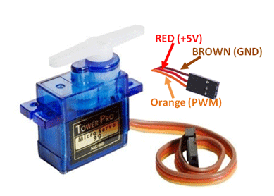
Here is the pinout of the servo motor
Here is the sample code for testing the servo motor
int servo = 10;

int angle;
int pwm;

void setup()
{
 pinMode(servo, OUTPUT);
}

void loop ()
{
 for (angle = 0; angle <= 140; angle += 5)  {
   servoPulse(servo, angle);  }
 for (angle = 140; angle >= 0; angle -= 5)  {
   servoPulse(servo, angle);  }
}

void servoPulse (int servo, int angle)
{
 pwm = (angle*11) + 500;      // Convert angle to microseconds
 digitalWrite(servo, HIGH);
 delayMicroseconds(pwm);
 digitalWrite(servo, LOW);
 delay(50);                   // Refresh cycle of servo
}
Here is the video output of the servo motor
OLED screen
An OLED (Organic Light-Emitting Diode) display is a type of display technology that utilizes organic compounds to emit light when an electric current is passed through them. OLED displays are known for their high contrast ratio, fast response time, wide viewing angles, and thin form factor.
Structure of an OLED Display:
- Organic Layers : OLED displays consist of multiple organic layers sandwiched between two conductive electrodes, typically made of glass or plastic substrates. These organic layers include an emissive layer, conductive layer, and substrate layer.
- Emissive Layer : The emissive layer contains organic compounds that emit light when an electric current passes through them. Different types of organic compounds are used to produce different colors (red, green, and blue) in RGB OLED displays.
- Conductive Layers : The conductive layers, usually made of transparent materials such as Indium Tin Oxide (ITO), serve as electrodes to apply voltage across the OLED layers.
- Substrate Layer : The substrate layer provides mechanical support and protection for the OLED layers. It is typically made of glass or plastic.
Working Principle of OLED Displays:
- Electroluminescence : OLED displays work on the principle of electroluminescence, where organic materials emit light in response to an electric current. When a voltage is applied across the OLED layers, electrons flow from the cathode (negative electrode) to the anode (positive electrode), causing the emissive layer to emit light.
- Pixel Control : OLED displays are made up of numerous individual pixels, each containing subpixels for red, green, and blue colors in RGB displays. By controlling the voltage applied to each pixel, the intensity of light emitted by the corresponding subpixels can be adjusted, allowing for precise control over brightness and color.
- Active Matrix vs. Passive Matrix : OLED displays can be categorized into active matrix OLED (AMOLED) and passive matrix OLED (PMOLED) based on the driving mechanism. AMOLED displays use thin-film transistor (TFT) technology to control each pixel individually, enabling faster response times and higher resolution. PMOLED displays, on the other hand, use simpler driving schemes but are typically limited in resolution and refresh rate.
Applications of OLED Displays:
OLED displays are used in various electronic devices and applications, including:
- Smartphones and tablets
- Televisions and monitors
- Wearable devices (smartwatches, fitness trackers)
- Automotive displays (instrument clusters, infotainment systems)
- Virtual reality (VR) and augmented reality (AR) headsets
- Industrial and medical displays
- Signage and advertising displays
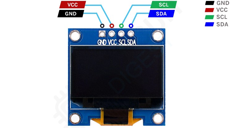
I2C (Inter-Integrated Circuit) :
- I2C is a popular serial communication protocol used for communication between integrated circuits.
- OLED displays can be interfaced using the I2C protocol, which requires only two signal lines: SDA (data) and SCL (clock).
- I2C allows multiple devices to be connected to the same bus, each with a unique address, enabling communication with several OLED displays using a single microcontroller.
- However, I2C communication may be slower compared to SPI, making it more suitable for applications with lower data transfer requirements.
Here is the pinout of the OLED screen
Here is the sample code for testing the OLED screen
#include <Wire.h>
#include <Adafruit_GFX.h>
#include <Adafruit_SSD1306.h>

#define SCREEN_WIDTH 128
#define SCREEN_HEIGHT 64
#define OLED_RESET -1 // Reset pin # (or -1 if sharing Arduino reset pin)

Adafruit_SSD1306 display(SCREEN_WIDTH, SCREEN_HEIGHT, &Wire, OLED_RESET);

void setup() {
  // Initialize OLED display with I2C address 0x3C
  if(!display.begin(SSD1306_SWITCHCAPVCC, 0x3C)) {
    Serial.println(F("SSD1306 allocation failed"));
    for(;;);
  }

  // Clear the buffer
  display.clearDisplay();

  // Set text size, color, and position
  display.setTextSize(1);
  display.setTextColor(SSD1306_WHITE);
  display.setCursor(0, 0);

  // Display text
  display.println(F("Hello, world!"));
  display.display();
}

void loop() {
  // Nothing to loop
}
Here is the video showcasing the testing process of the OLED screen.
Buzzer
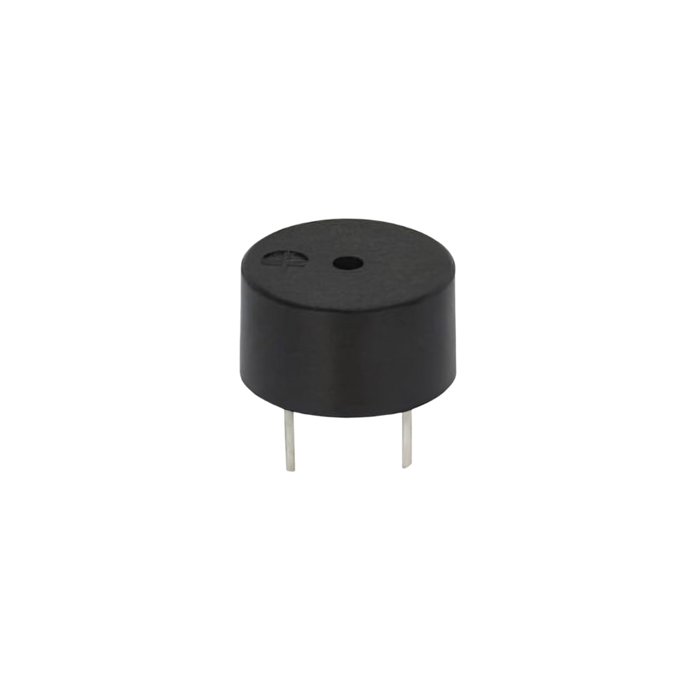
A buzzer is a small electronic device commonly used to produce sound when an electric current passes through it. It serves as an audible indicator in various electronic circuits and devices.
- Operating Principle : The primary operating principle of buzzers is the piezoelectric effect, where the piezoelectric crystal undergoes mechanical deformation when a voltage is applied, resulting in vibration and sound production.
PWM signals can be used to control the pitch or frequency of a buzzer. A buzzer typically produces sound by rapidly toggling a voltage on and off at a certain frequency, creating vibrations that generate audible sound waves. Here's how PWM signals control the buzzer:
- Frequency Control : The frequency of the PWM signal determines the pitch of the sound produced by the buzzer. Higher frequencies produce higher-pitched sounds, while lower frequencies produce lower-pitched sounds.
- Duty Cycle Control : The duty cycle of the PWM signal controls the loudness or volume of the sound produced by the buzzer. A higher duty cycle (i.e., longer duration of the ON state compared to the OFF state within each period) produces a louder sound, while a lower duty cycle produces a quieter sound.
Overall, buzzers are versatile components commonly used for auditory alerts and indications in electronic systems.
The buzzer can be controlled in two ways:
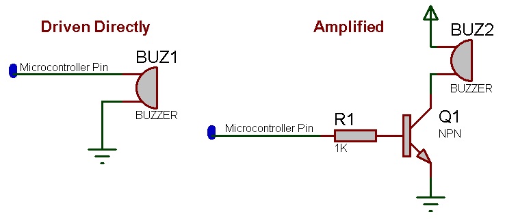
- Direct Control by Microcontroller Pin : The buzzer can be directly connected to a microcontroller pin. By toggling the pin's state (HIGH or LOW), the microcontroller can control the buzzer's operation. This method is simple and straightforward, but it may have limitations in terms of the current sourcing capability of the microcontroller pin.
- Control via MOSFET : Alternatively, the buzzer can be controlled using a MOSFET (Metal-Oxide-Semiconductor Field-Effect Transistor). The microcontroller can drive the MOSFET's gate pin to control the flow of current through the buzzer. This method allows for higher current handling capabilities and can be advantageous when the buzzer requires more current than the microcontroller can provide directly. Additionally, using a MOSFET provides isolation between the microcontroller and the buzzer, which can be beneficial for noise reduction and protection of the microcontroller.
Both methods have their advantages and can be chosen based on the specific requirements of the application, such as current requirements, noise considerations, and isolation needs.
Here is the sample code that can be used
#include <avr/io.h>
#include <util/delay.h>

#define F_CPU 8000000UL // ATtiny1614 operates at 8MHz

#define BUZZER_PIN 4 // PA04

void buzzer_init() {
    // Set PA04 as output
    PORTA.DIRSET = PIN4_bm;
}

void buzzer_on() {
    // Set PA04 high to turn on the buzzer
    PORTA.OUTSET = PIN4_bm;
}

void buzzer_off() {
    // Set PA04 low to turn off the buzzer
    PORTA.OUTCLR = PIN4_bm;
}

int main() {
    // Initialize buzzer
    buzzer_init();

    while (1) {
        // Turn on the buzzer
        buzzer_on();

        // Wait for some time
        _delay_ms(1000);

        // Turn off the buzzer
        buzzer_off();

        // Wait for some time
        _delay_ms(1000);
    }

    return 0;
}
Here is the sample video demonstrating the buzzer buzzing with the PWM signal, controlled by the MOSFET.
Neo pixel
Neopixel LEDs, also known as WS2812 or WS2812B LEDs, are a type of addressable RGB LED Neopixel LEDs feature an integrated controller chip (typically the WS2812 or WS2812B) embedded within the LED package. This controller manages the color and brightness of each individual LED and communicates with external microcontrollers or controllers .
One of the key features of Neopixel LEDs is their addressable design, which allows each LED in a chain to be controlled independently. This means that multiple Neopixel LEDs can be daisy-chained together, and each LED can be assigned a unique color and brightness level.
Neopixel LEDs use a simple serial communication protocol to receive control signals from external microcontrollers or controllers. The most common protocol used is the "WS2812 Protocol," which consists of sending a series of pulse-width modulated (PWM) signals to the data line.
Provided below is the pinout diagram for the NeoPixel SMD LED.
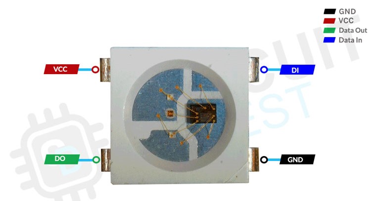
NeoPixel SMD LEDs emit different types of colors by independently controlling the intensity of red, green, and blue light emitted by each individual LED within the module. This is known as RGB (Red, Green, Blue) color mixing. Here's how it works:
Each NeoPixel LED module contains three separate LEDs: one red, one green, and one blue. These LEDs are typically very small and integrated into a single package.
By adjusting the brightness of each individual LED—red, green, and blue—different colors can be created.
Various shades and hues can be achieved by adjusting the brightness levels of each LED component
What makes NeoPixel LEDs particularly versatile is their addressable control. Each LED within the module has its unique address and can be individually controlled. This means that you can set the brightness of each red, green, and blue LED separately for each NeoPixel in a chain, allowing for precise control over the color and brightness of each LED.
Sample code
// ATtiny1614 pins definitions
#define NEOPIXEL_PIN 1  // Pin connected to the NeoPixel strip (PA3)
#define NUM_LEDS 3      // Number of NeoPixel LEDs in the strip

// Function prototypes
void neopixelSetColor(uint8_t r, uint8_t g, uint8_t b);
void neopixelShow();
void neopixelClear();

void setup() {
  // Set NeoPixel pin as output
  PORTA.DIRSET = PIN5_bm;

  // Initialize NeoPixel
  neopixelClear();
  neopixelShow();
}

void loop() {
  // Fill the first LED with red color
  neopixelSetColor(255, 0, 0);
  neopixelShow();
  delay(500);

  // Fill the second LED with green color
  neopixelSetColor(0, 255, 0);
  neopixelShow();
  delay(500);

  // Fill both LEDs with blue color
  neopixelSetColor(0, 0, 255);
  neopixelShow();
  delay(500);
}

// Function to set the color of the NeoPixel LEDs
void neopixelSetColor(uint8_t r, uint8_t g, uint8_t b) {
  uint32_t grb = ((uint32_t)g << 16) | ((uint32_t)r << 8) | b;

  // Disable interrupts
  cli();

  for (int i = 0; i < NUM_LEDS * 24; i++) {
    if (grb & 0x800000) {
      PORTA.OUTSET = PIN5_bm;         // Set pin high
      __builtin_avr_delay_cycles(8);  // ~250 ns delay
      PORTA.OUTCLR = PIN5_bm;         // Set pin low
      __builtin_avr_delay_cycles(4);  // ~125 ns delay
    } else {
      PORTA.OUTSET = PIN5_bm;         // Set pin high
      __builtin_avr_delay_cycles(3);  // ~94 ns delay
      PORTA.OUTCLR = PIN5_bm;         // Set pin low
      __builtin_avr_delay_cycles(9);  // ~281 ns delay
    }
    grb <<= 1;  // Shift to next bit
  }

  // Enable interrupts
  sei();
}

// Function to show the NeoPixel LEDs
void neopixelShow() {
  // Do nothing, as the LEDs are updated immediately in setColor function
}

// Function to clear the NeoPixel LEDs
void neopixelClear() {
  // Clear NeoPixel data
  neopixelSetColor(0, 0, 0);
}
Following the code upload, I noticed that only one NeoPixel LED is operational. I need to figure out why the other isn’t functioning. Attached below is a sample video demonstrating the functionality of the NeoPixel LEDs.
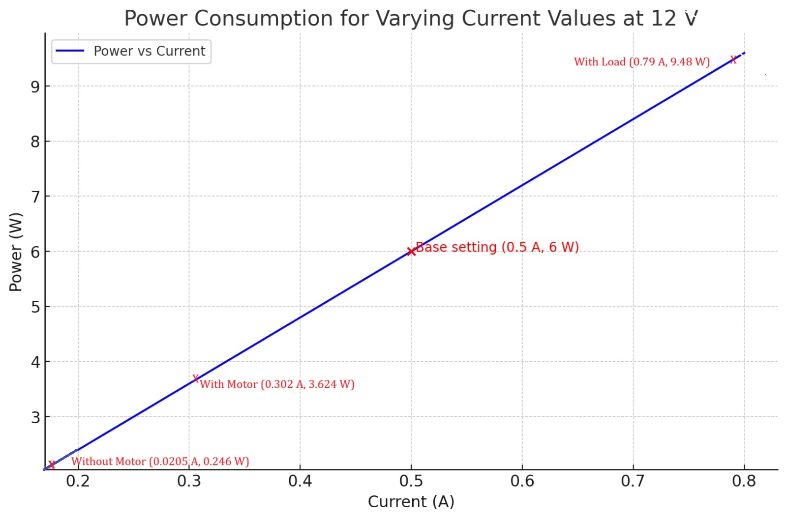
Group Assignment: click here.
- This week's group assignment was to measure the power consumption of an output device. We chose Stepper Motor as the output device.